A Resin Printing Handbook
I'm often asked by curious novices, 'where do I start?'; 'what is the best printer?' I believe these inquiries arise less from my expertise in the hobby, but rather from a lack of approachability in the resin printing community. Newcomers are often warded off by vague safety concerns or elitism from community regulars. Anyone with an ounce of determination is capable of stereolithography, or resin printing. Let's take a fresh perspective.The 'lith' in SLA refers to the Greek root meaning 'stone'. We use a resin called a photopolymer, where 'photo' refers to light. In essence, the printer uses light to turn liquid resin into 'stone', a solid object. The most notable ways of executing this include an LCD screen, which shines an image of ultraviolet light for a couple seconds, and the less common Digital Light Processing, which is effectively a projector of ultraviolet light. When choosing a printer to purchase, you will likely find that LCD models are cheaper.
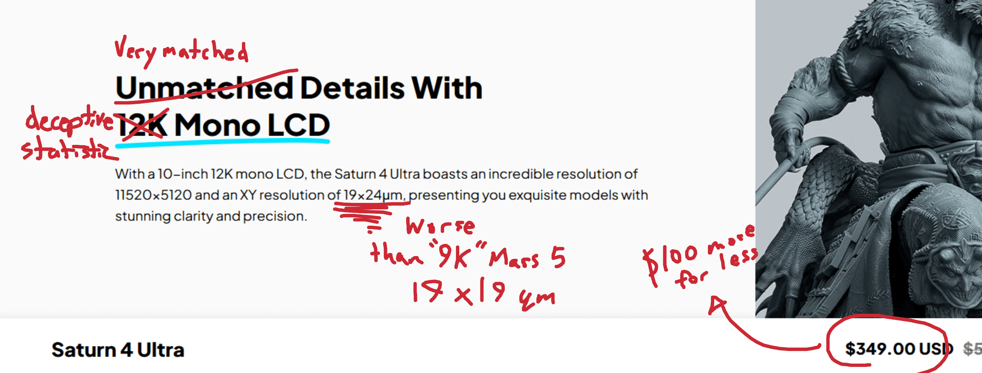
What do I actually need to get started? Of course, you will need a printer. Choose a resolution and size based on your needs and budget. I personally use an Elegoo Mars 3 Pro, but it may not be your preference. Be wary of the marketing term '4K/8K/16K' enjoyed by companies like Elegoo, as this figure is unrelated to resolution. If you want detail, look for the pixel size in micrometers. Naturally you will also need resin, so look for your desired photopolymer color in the right wavelength (don't worry, most will be). What is often forgotten from resin printing guides is the auxiliary supplies needed after the print is done. This includes roughly a gallon of pure isopropyl alcohol, a washing/cure station often sold by the same printer company, scrapers, and any safety equipment. That necessitates nitrile gloves, glasses, and respiratory protection.
A quick word on safety -- while the community loves to fearmonger, there is certainly a valid reason to take cautionary actions. Resin fumes contain Volatile Organic Compounds (VOCs), similar to smoke exhausted by flames. It isn’t fun stuff, but it also isn’t the neurotoxin you’ll see in Portal 2. I use a VOC-rated respirator, as a standard N95 mask is not a great solution long term. Resin itself is a sticky chemical that preferably should not contact bare skin, but a thorough rinse should take care of most residue.
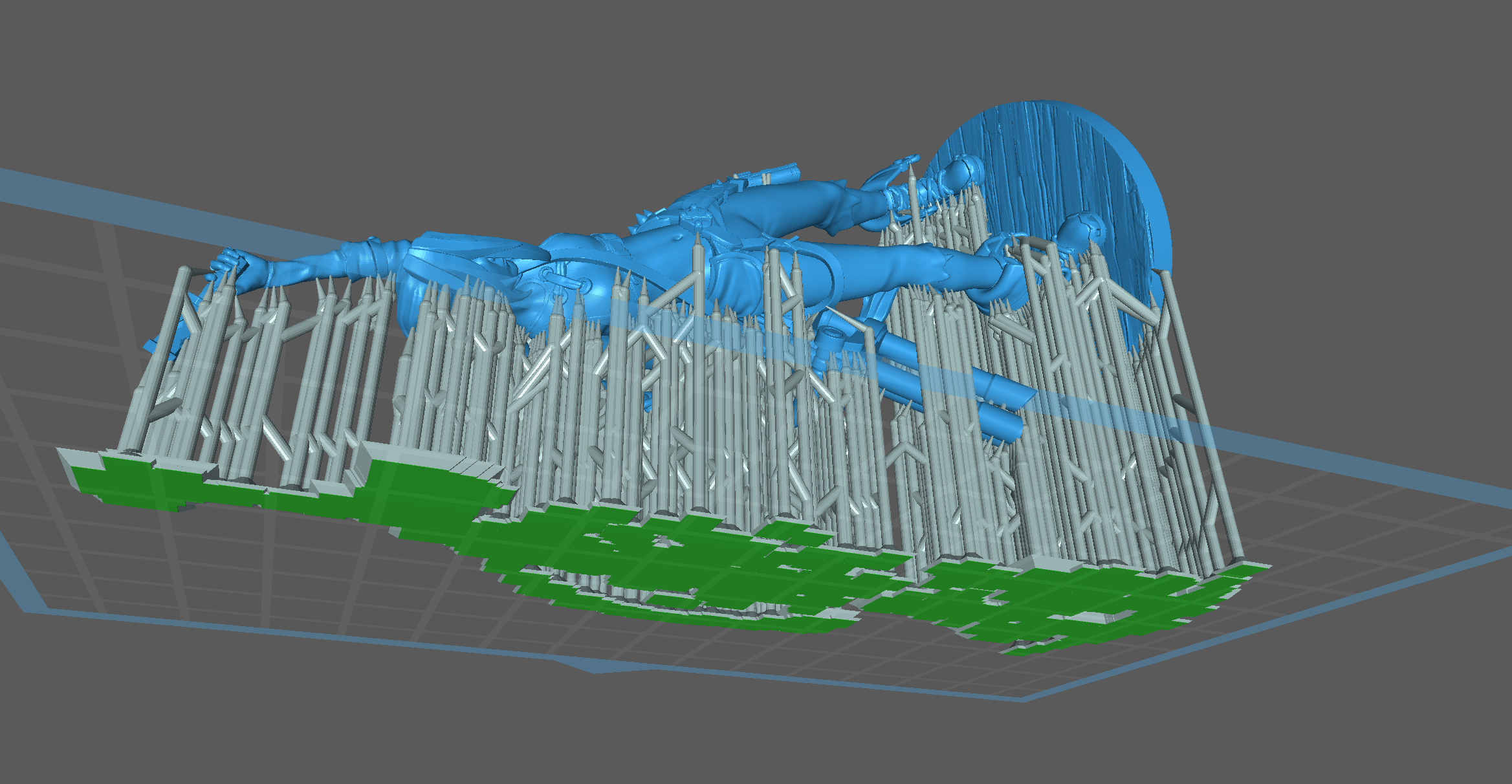
With all the preliminaries out of the way, let’s talk about the fun stuff – printing a model. Now this is no plug and play operation; resin printing involves preparation, printing, and postprocessing. For the first phase, enthusiasts will often spend most of their time within Chitubox creating supportive structures for the model. The software will highlight unsupported areas in red. We are in perpetual conflict with islands – essentially upside down protrusions on the model that produce free floating resin bits if left unchecked. I will spend upwards of six hours (depending on the complexity) during this phase adding supports to ensure no deformities occur in the model. In Chitubox we can also hollow the model to save resin and cleverly orientate it to minimize supports. After Chitubox I like to export the file into UVTools, which is a powerful open source program that checks faulty pixels across thousands of layers. UVTools will warn us of missed islands and potential suction cups, which are caused by an incorrect hollowing and require a drilled hole to alleviate. Once you are confident that the model is prepared for printing, you can flash the .ctb file into the printer with a FAT32 formatted USB stick.
After completion, it is time to equip the safety equipment and extract the printing bed along with the model. Be careful as to not let the liquid drip off the bed and stain any clothes. Wash off any liquid resin with IPA at the aforementioned station for around 2-3 minutes. The model is now safe enough to clean up. Instead of attacking the plate with a scraper like many novices tend to do, try heating up the edge where the supports meet the bed. I like to use a hairdryer, but a heat gun or even just warm water also does the job. Without using significant force, lever off the model with the scraper. It might be easier to first disconnect the supports from the model with the same heating process and careful wire cutting. At the same time, watch for any shiny surfaces that indicate liquid leakage and clean them up before curing. I know, it’s an extremely messy process. Patience is key to achieving a pristine final product. Once the model is free from the shackles that are the supports, cure it in a UV light for 1-2 minutes. Your fancy model is safe to touch, and onlookers of the beauty are none the wiser of your toils.
Have fun and safe printing,
Andrew
1/30/25
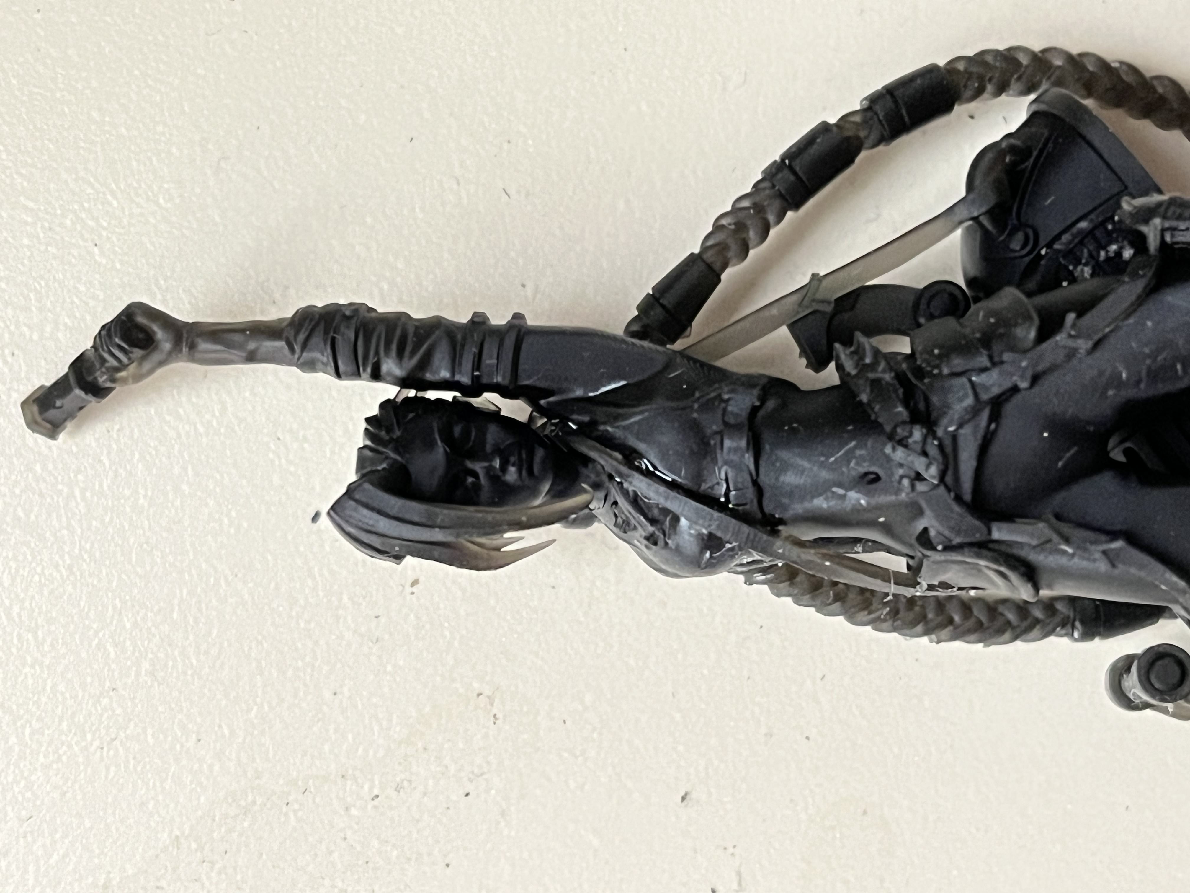

Jinx from 'Arcane' Translucent Flower illuminated by UV
A review of the effectiveness of additive manufacturing of carbon fiber-reinforced polymers for aerospace applications
Abstract
Researcher: Andrew Stroub
Presentation Title: A review on the effectiveness of additive manufacturing of carbon fiber-reinforced polymers for aerospace applications
Presentation Type: Paper
This research paper investigated the mechanical properties, anisotropy, and relevance of carbon fiber-reinforced polymers (CFRPs) fabricated using additive manufacturing (AM), particularly in the aerospace sector. While researching CFRPs, a divergence in the properties of parts made from conventional processes compared to those produced with AM was found. These differences impede the integration of AM into the aerospace industry.
This research illustrates the design flexibility and weight reduction achieved by additive manufacturing, while emphasizing consideration of the methods’ limitations. FFF, the most common AM technique, has been adopted for the production of Unmanned Aerial Vehicles (UAV) CFRP components, where it shines in rapidly prototyping complex geometries. On the other hand, the Selective Laser Sintering (SLS) technique fares better in anisotropy, resulting in parts that have more reliable strength metrics due to consistent fiber alignment. While additive manufacturing can be more cost-effective than a more conventional approach, AM CFRPs perform significantly worse in terms of tensile strength and elastic modulus.
The work in this study is significant due to the increasing demand in the aerospace industry for cheaper and more lightweight CFRP components. Additive manufacturing underperforms in crucial aspects – namely mechanical properties and anisotropy – while showing promising capability in aerospace applications. Based on this study’s findings, researchers should aim to minimize the anisotropy of AM CFRPs in order to meet reliability standards. Researching composite materials has provided insight into the development of aircraft and modern technology that people often take for granted.
Introduction
Air travel has become one of the most globally standardized systems of transportation. Due to its popularity, minimizing weight and maximizing reliability is a critical demand for aircraft materials. Composites offer high strength, stiffness, and fatigue resistance while retaining lower weight than comparable metals.1 Due to these qualities, composites have been substantially integrated into the aerospace industry.2
One of the most widely used composites is carbon fiber reinforced composites or CFRPs. CFRPs are often categorized by their fiber length – short or long/continuous. However, concerns have been raised over the feasibility of conventional manufacturing methods for CFRPs, particularly in low-volume applications.3 Additive manufacturing (AM) has emerged as a potential solution for fabricating CFRPs with improved design freedom. AM, the process of building material layer-by-layer, can considerably lower entry costs for the production of CFRPs. Standard methods among AM include Fused Filament Fabrication (FFF), the most researched and widespread technique, and Selective Laser Sintering (SLS), which uses a laser to melt layers of material powder together.4 Currently, CFRPs produced with AM perform lower in key strength metrics than conventional composites.1 This paper will explore whether the issues of AM methods can be ameliorated.
This review paper investigates how aspects of CFRPs in conjunction with a polymer base, including the mechanical properties, anisotropy, and application in the aerospace industry, can be improved upon when integrating AM methodology. The aim is to find a useful trade-off between cost-effectiveness and the aerospace viability of fatigue-resistant materials and manufacturing processes. The mechanical properties of AM CFRPs will be compared against conventional counterparts to provide a reference perspective. The impact of anisotropy on the part resulting from AM techniques will be discussed, and specific applications in the aerospace sector will be considered. Finally, critical areas for future research in the CFRP field will be highlighted, and industry takeaways will be recommended.
Background
The purpose of this paper is to review how composites evolved leading up to CFRPs within the context of aerospace applications. In the past half-century, fiber composites have undergone a series of research and refinement, leading to the modern form of CFRPs. Numerous organic and synthetic fibers have been tested, including aramid, paper, wood, asbestos, glass, and carbon fiber.3 CFRPs have attracted interest for their high tensile strength, fatigue resistance, and lightweight nature, among other qualities. Composites are produced by pulling extruded raw material into fibers and mixing them with some resin or polymer base, known as the matrix. The mixing process is either done prior to or during the part manufacturing process. Researchers have experimented with altering the precursor material for the fiber, discovering that tensile strength and temperature resistance can vary greatly.5
One of the first methods developed to manufacture CFRPs is known as hand lay-up (HLU). HLU involves rolling resin onto dry fiber in successive layers so that each layer cures within the mold. However, HLU is only effective in low volumes.6 Die, and injection molding methods have been developed to press CFRP parts at large scales, but these techniques are often limited to relatively simple forms.7Additionally, these molds are conventionally manufactured out of aluminum or steel. Both require CNC machining, with the former lasting only a few thousand cycles, while the latter is significantly more expensive.3 The manual limitation of HLU and the high investment needed for molds have prompted interest in newer and more flexible manufacturing options, such as AM.
Additive manufacturing has risen from the demand for an automated, flexible, and cost-effective method for producing CFRP parts. While not initially intended for composites, printers can be adapted to use fiber-reinforced filament or pellets. AM techniques allow for designs, unlike any other conventional method. In the following section, the mechanical outcomes of AM will be stacked up against conventional CFRPs to observe their range of strength.
Mechanical Properties of Additively Manufactured CFRP Composites
In order to determine the feasibility of applying additively manufactured CFRPs to aerospace design, the relevant mechanical metrics should be understood in comparison to the appropriately similar conventionally manufactured CFRP. To be a competitive candidate in the aerospace industry, the AM composite is required to have a high strength while remaining lighter than aluminum or steel. The sustainability of the composite depends on a variety of factors, including tensile strength, elastic modulus, and shear resilience. Tensile strength considers the maximum force a material withstands when being pulled apart, while elastic modulus describes how much a material resists being bent elastically, or non-permanently.4 The elastic modulus is generally expressed with Young’s modulus. Interlaminar shear strength (ILSS) refers to the amount of lateral force necessary to rip apart the layers, or laminates, within the composite material.8
The rule of mixtures allows the comparison of CFRPs only similar in one material, as long as the differing material has a negligible effect on the critical metric. For instance, tensile strength and elastic modulus can be reasonably compared between two composites of differing polymer matrices, as the fiber has the most effect on overall strength.3 In a study, Zhou et al. investigated the strength of conventional injection-molded polyacrylonitrile-based CF, and found the tensile strength to be 70 MPa.9
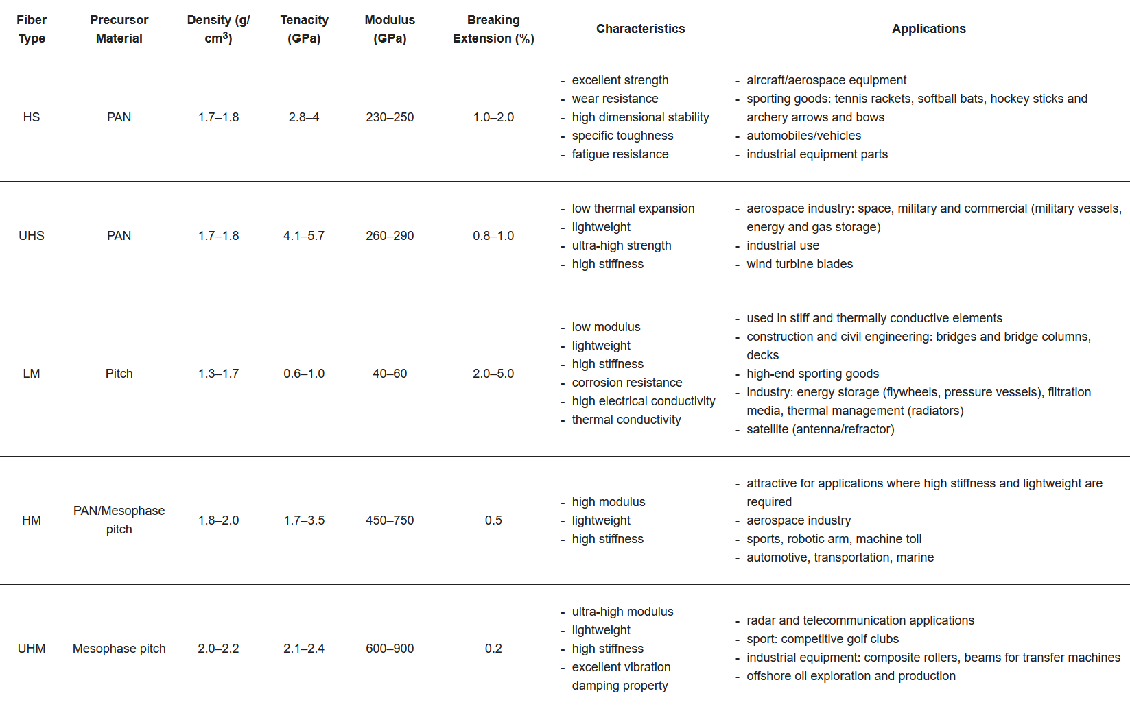
Table 1 presents the elastic modulus of various grades of conventionally manufactured carbon fiber.5 To establish a benchmark for later comparison, only the tenacity and modulus columns for each CFRP will be taken into account. For aerospace applications, both a high modulus and high tensile strength are necessary.
Table 1. Mechanical characteristics and applications of high strength, high modulus, etc. conventional carbon fiber.
Tekinalp et al. investigated the effect of fiber weight on the strength of a CF-ABS (acrylonitrile butadiene styrene) blend using FFF additive manufacturing. The tensile strength and modulus of 10%, 20%, 30%, and 40% fiber weight are given in Table 2, respectively. The tensile strength increases marginally with more fiber, with a range in strength around 50-65 MPa. It should be noted that the increase in the fiber proportion does not necessarily result in greater mechanical properties, which has a peak in elastic modulus of around 30 percent.
Table 2. Summary of experimentally-determined strength quantities of AM CF-ABS.10
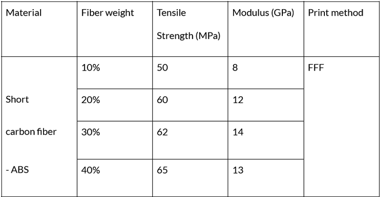
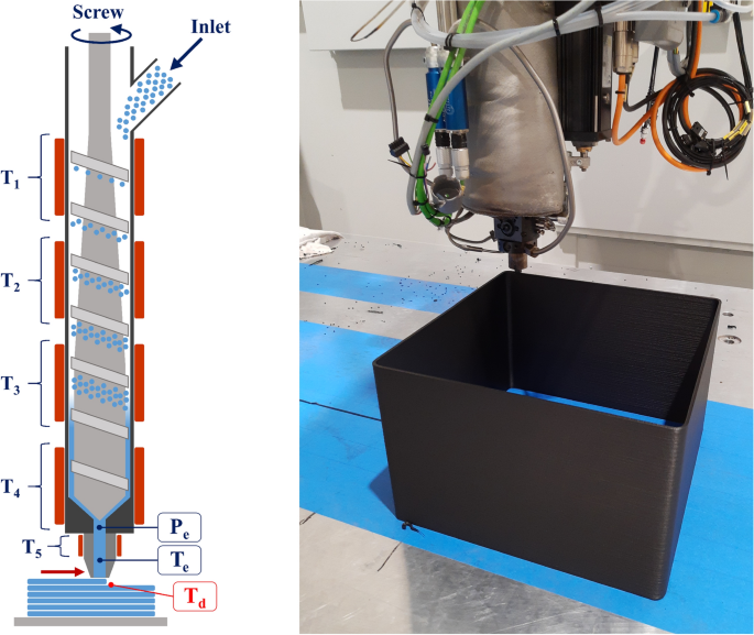
While the addition of fiber is a substantial improvement from the base polymer, AM CFRPs achieve a substantially lower tensile strength and modulus than the conventional counterpart. The optimal tensile and modulus properties for short CFRPs were found to be a polyamide-12 matrix at 50% fiber weight, measured to be 115 MPa and 4.75 GPa, respectively.4 The choice of fiber, continuous/short, also plays an important role in the mechanical properties of the printed CFRP. Liu et al. demonstrated that a nylon-based continuous CFRP at 50.2% fiber wt. has an extremely high tensile strength and modulus of 735.7 MPa and 79.5 GPa, respectively.11 Both tensile and modulus metrics are critical in aerospace applications, though modulus has more widespread demand. Many aerospace components, including wing spars, frames, and linkages, have moment loads requiring high stiffness, or high modulus. The introduction of continuous fiber requires equipment beyond just FFF. Liu et al. use a specialized micro-screw in-situ process to properly impregnate the polymer pellets, as shown in Figure 1. While continuous AM CFRPs are appealing for their high performance, the difficulty of manufacturing due to higher entry costs and the potential effect on anisotropy should be considered.
Figure 1. A depiction of a CMS screw extrusion additive manufacturing unit.12
Yavas et al. examined the interlaminar shear strength of combining continuous and short FFF CFRP layers in varying stacking sequences, altering the anisotropy, or uniformity, of the object. A 48-layer continuous CFRP stack and a hybrid 24/24 continuous and short mix were found to have an ILSS of 40.9 MPa and 24.4 MPa, respectively. In the hybrid mix, consecutive layers of short CFRP resulted in a greater ILSS than alternating types, showing the significance of fiber continuity on interfacial bonding. This suggests that hybrid-capable manufacturing equipment may not be necessary for aerospace applications.
As mentioned previously, the proportion of fiber to polymer matrix is a critical factor for effective AM CFRP parts. An extraordinary percentage of carbon fiber induces a deteriorated microstructure between layers in the form of voids, as the polymer ‘glue’ is not substantial enough to contain the structure. The FFF method is particularly susceptible to voids due to an elliptical extrusion shape at the nozzle output, with an estimated 7-11% of nylon CFRP volume attributed to voids.4 Standard FFF parts with no reinforcement are expected to have void volume levels of around 3-8%, depending on printing speed.13 Studies show that the usage of a square nozzle can reduce void content from up to 30% to as low as 7%, verified by scanning electron microscopy (SEM) examinations.14 Post-processing techniques like compaction rolling and post-sintering have also been proven effective at ameliorating the microstructure and reducing voids, with the latter even increasing tensile strength by 15%.15,16 However, these treatments come at the trade-off of adversely impacting dimensional accuracy, which is often a strict demand in aerospace applications.4 Insufficient accuracy results in part rejection, wasting resources. Manufacturers look for consistency in production, which is why anisotropy is a highly prevalent concern in AM CFRPs. A material is characterized as anisotropic if its structure is not uniform, effectively varying the mechanical properties depending on the orientation of the applied load.
Anisotropy
Anisotropic qualities are preferably avoided when designing a part, as it introduces another unreliable factor to consider. Objects produced by additive manufacturing methods, particularly FFF, are often anisotropic as a result of seams created by the buildup of material layers.4
Jiang and Smith demonstrated the impact of anisotropy through a series of tensile tests on FFF CFRP bars, finding that the composite yielded higher tensile strength and modulus at the 0-degree loading orientation. In fact, the reinforcement of CF 'coupons' was shown to decrease tensile strength when the beads did not align with the loading direction.17 The anisotropic quality of composites has been known to cause part failure in the aerospace industry, especially due to interlaminar cracks.18
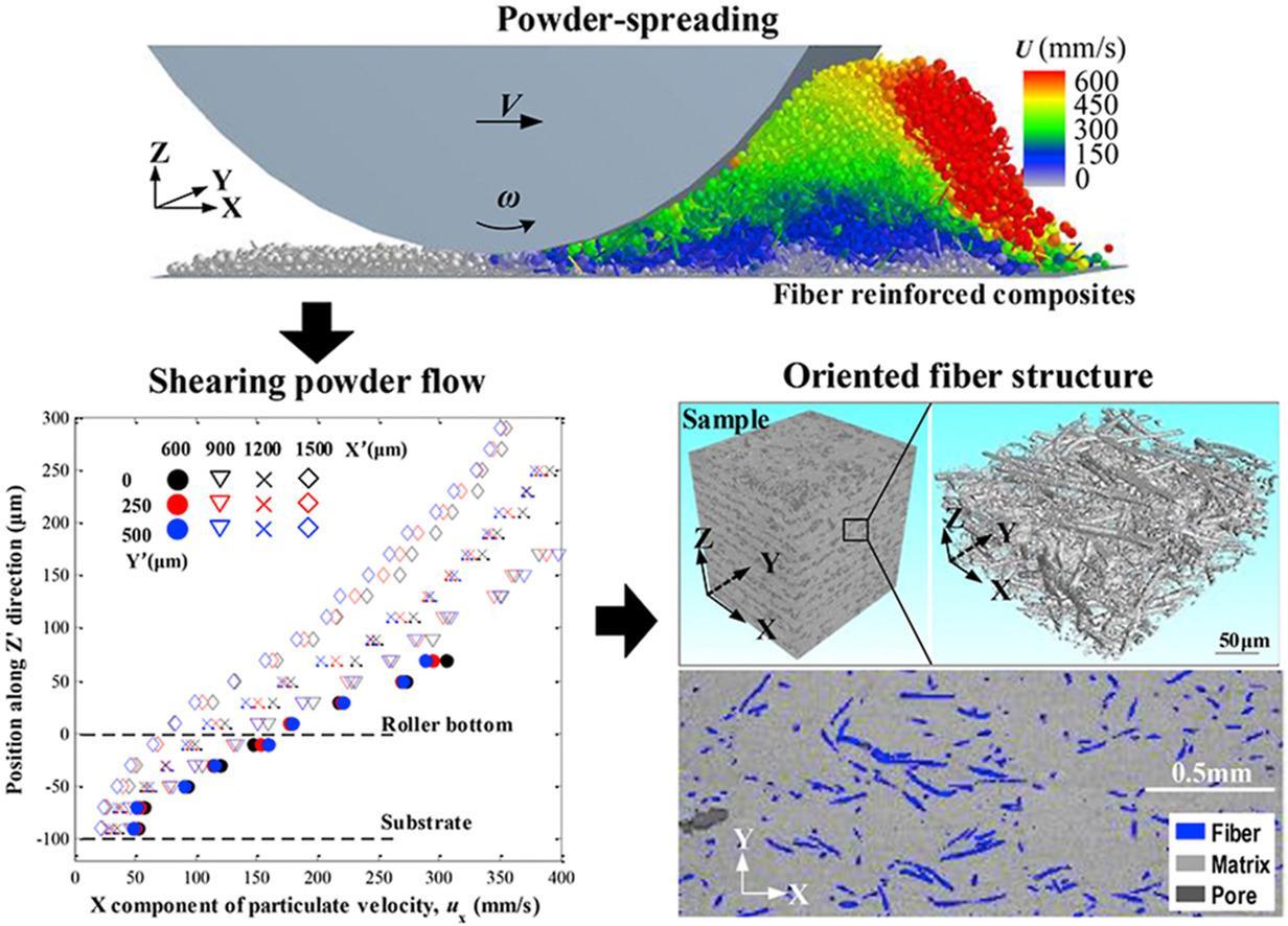
Many considering additive manufacturing often look to SLS over FFF for potential upsides, including the lack of supports, a wider range of materials, and more. Hu et al. observed the anisotropy of CFRPs produced through SLS, determining that a large proportion of the fibers are consistently aligned in one direction.19 This quality may be an attractive alternative to the volatility of FFF fiber alignment for certain design constraints, as the strength is concentrated in a single direction. Even though the part strength is not uniform to all loads, this directional consistency could be useful for aerospace parts designed to undergo thousands of load cycles, particularly if the loading direction experienced in the field is known prior to design. The authors concluded that the consistency was due to the powder distribution system of each SLS layer, as shown in Figure 2, making this AM technique reliable for producing CFRPs for aerospace load requirements. Additionally, the SLS method entails other optimal features, such as the lack of support and reliable, albeit grainy, surface quality. The former reduces part post-processing time, saving costs for aerospace applications. This cost efficiency highlights how process advantages can help compensate for the documented mechanical limitations of additive manufacturing methods.
Figure 2. 3D visualization of SLS powder spreading and fiber particulate velocity.20
Direct Applications in Aerospace
Although CFRPs produced with additive manufacturing have yet to be proven successful in large-scale industrial applications. Conventional CFRPs are an established component in commercial aircraft, including usage in the rudder, stabilizer, karman, radome, and more on the Airbus A320 alone. Processes such as CFRP mold tooling and Unmanned Aerial Vehicle (UAV) landing gear prototyping, display how AM CFRPs are already being tested in aerospace-relevant contexts. CFRPs are highly sought after for their lightweight, high-temperature capabilities and corrosion resistance. Each kilogram of weight reduction could save up to 120 L of fuel, which is particularly important with modern CO2 emission regulations.21 Additive manufacturing of metal has also been extraordinarily effective in aerospace, with NASA using AM methods for 80% of rocket engine manufacturing.4
There are several drawbacks and concerns regarding the integration of both CFRPs and additive manufacturing in the industry. As the scale of manufacturing grows, specialized equipment becomes necessary, adding initial costs that can deter prospecting companies. The issues prevalent in AM are carried over and become more pronounced with CFRPs, including printing errors like elephant foot, void formation, poor overhang surfaces, low accuracy, and inconsistency.22 Although CFRPs are broadly gaining popularity in aircraft construction, there are concerns about reliability. Conventional parts made with manual tape layup introduce human error. Any deformities in the manufactured part result in rejection for use in aerospace, an industry where quality control is strict.23 It remains to be seen if the integration of AM will reliably decrease human error of composite parts.
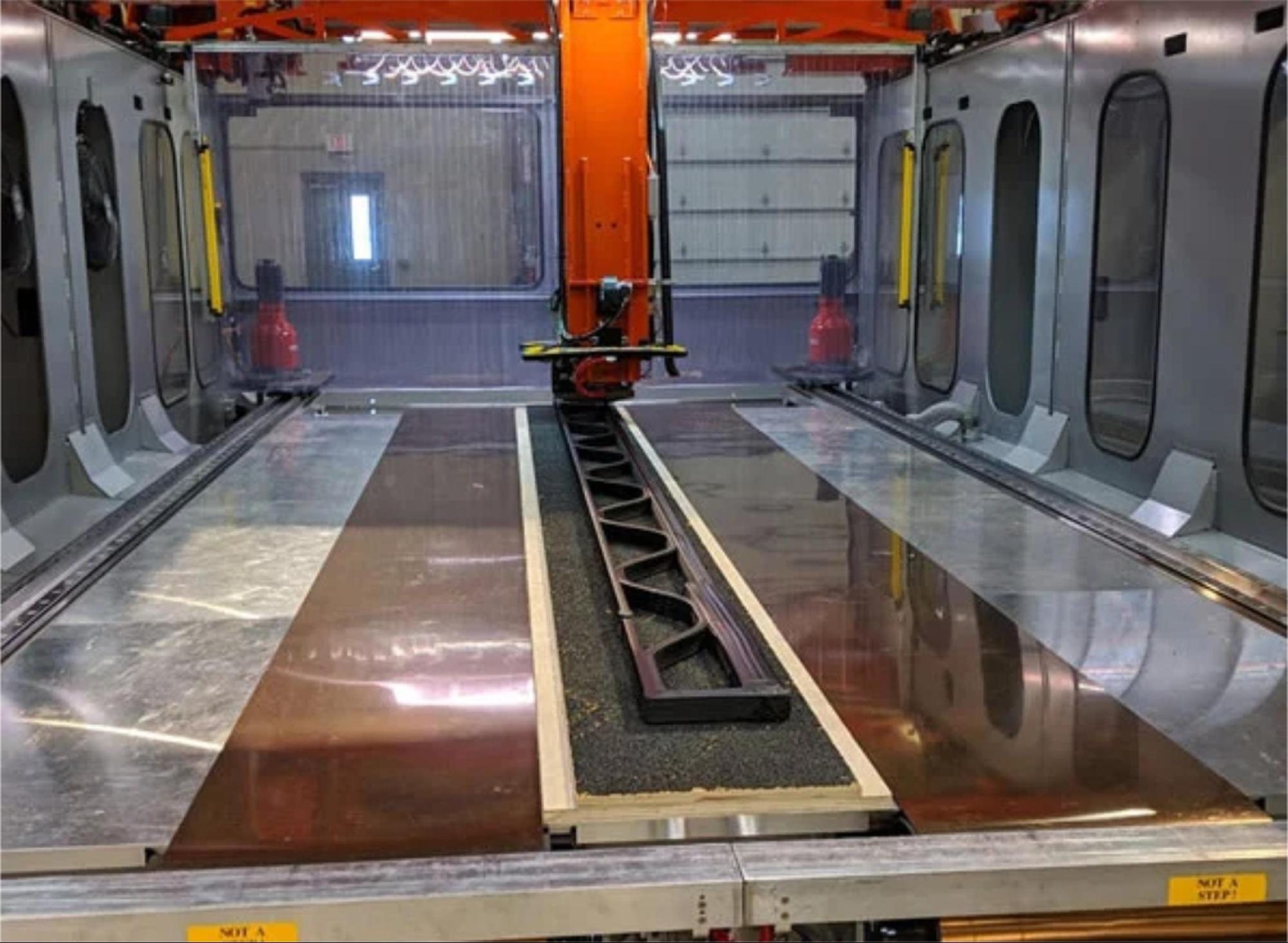
Despite concerns in the developing field of AM CFRPs, Bell Textron has used the Thermwood LSAM to manufacture large CFRP molds for six-meter helicopter rotor blades, as shown in Figure 3. Although the mold is not itself a flight component, its use in the fabrication of rotor blades indicates that AM CFRPs can meet demanding conditions in the aerospace industry. The CFRP material withstands the high pressure and temperatures demanded by the molding and autoclave sterilization process. This material choice avoids incurring the high costs of metals traditionally used for molding.4
Figure 3. ABS-CFRP blend is used to produce a 20-foot mold with the Thermwood LSAM, a helpful machine for large dimensions without the need for multi-piece assembly.24
One of the most prominent focuses in aerospace design is the landing gear of an aircraft, as they necessitate high impact resistance and low weight. Goh et al. investigate the tensile and stiffness performance of UAV landing gear components made with continuous AM CFRPs. AM methodology was found to be advantageous for the creation of topologically optimized shapes, whereas conventional techniques lack the capability of complex geometry. The authors took into account the resulting FFF anisotropy when preparing the design. A fatigue study was conducted, showing that under loads of 89% and 78% of the ultimate tensile strength, the CRFP performs for 450 cycles and 238 thousand cycles, respectively, before failure. However, the 3D printed solution appeared to underperform its CFRP theoretical counterpart in reaction force (N) over displacement, with the authors concluding that the disparity stemmed from imperfections of the printed surface. While strength suffered, the ability to produce complex geometry with minimal material loss allows the AM technique to be a valuable compromise in this application.
Additive Manufacturing Performance
All manufacturing methods have drawbacks, including additive manufacturing. Three factors can be considered — the strength of the part, e.g., by tensile or elastic metrics, the effect of anisotropy by fiber alignment, and the design flexibility allowed by the technique.
Due to a relatively high fiber weight fraction, the aforementioned continuous fiber FFF systems likely produce the most similar CFRP parts compared to conventional standards in terms of tensile strength. Continuous AM CFRPs are the optimized option when high mechanical strength is desired, with the added benefit of AM flexibility. In general, AM CFRPs are limited to a fiber content of 40-50% due to the demands of the extrudable matrixphase of manufacturing certain materials, i.e., plastic.25 For reference, conventional CFRPs achieve the apex of elastic strength at 50-70%.
Minimal anisotropy is best achieved by the aforementioned SLS technique, allowing reliable unidirectional fiber alignment that can be accounted for when preparing the design.20 However, SLS comes at the compromise of lackluster surface quality, which is prevalent throughout AM CFRP techniques due to a disproportionate fiber content or poor optimizations in the printer settings.4 Some machines like the MarkOne attempt to solve this by printing object perimeters with fibreless material. However, proprietary filament is required.26 Relying on proprietary equipment may eventually lead to a rise in production costs, so a trade-off between open sourcing and valuable AM features should be taken into account.
The most significant advantage gained by AM methods is the flexibility to create complex geometries that are otherwise only possible with excess material waste. Azarov et al. explored the effectiveness of a triangular infill lattice for weight reduction on a CFRP drone frame. While comparable frames of the same material range from 130-230g, this study achieved only 75g with the FFF method.27 Additionally, the number of required fasteners for assembly is minimized by manufacturing the frame in one single process. While FFF and SLS are both excellent options for internal structures, SLS has the added benefit of straightforward overhangs with zero supports, as the preceding powder layer acts as a bed for the next.28
Conclusion
This review examined how additive manufacturing could help open avenues for CFRP usage in the aerospace industry in three key areas – mechanical metrics, anisotropy, and aerospace relevance – while taking into account a balance between strength and consistency. Additive manufacturing is at the forefront of CFRP development, with FFF and SLS placed as some of the most researched methods. FFF machines have the lowest entry cost of any AM branch, but the tensile and stiffness metrics suffer severely compared to standard CFRPs due to low fiber content, poor microstructures, or machine inaccuracy. FFF remains useful for part designs where flexibility and low weight hold priority over maximum strength. Purpose-built machines using similar extruding technology, like the LSAM and continuous fiber printers, appear to withstand high stresses and numerous fatigue cycles standard in aerospace applications. A primary reason for CFRP usage in aircraft amounts to its lightweight quality. While strength is lacking, significant weight reduction can be achieved through internal structures in the design, made possible by AM flexibility.
Anisotropy, widely considered to be the major drawback of AM methodology, can work in the favor of the designer, as demonstrated by the consistent fiber alignment of SLS printing. It is worth considering that the dimensions of SLS machines are more limited than FDM, meaning significant components such as wings may not be practical with this method. Manipulating the orientation so that the load is aligned with the fiber is effective at mitigating interfacial failures in UAV components.
Research in the field is recommended to focus on minimizing and wielding the anisotropy of additively manufactured CFRPs rather than attempting to remove an inherent behavior. Minimized anisotropy is particularly vital for meeting aerospace reliability standards. Machine parameters should be further optimized to improve the mechanical reliability of the process in order for the methodology to appeal to aerospace criteria.
References
- Ning, F., Cong, W., Qiu, J., Wei, J. & Wang, S. Additive manufacturing of carbon fiber reinforced thermoplastic composites using fused deposition modeling. Compos. Part B Eng. 80, 369–378 (2015).
- Biron, M. Thermoplastics and Thermoplastic Composites. (Elsevier, London, 2013).
- Rajak, D. K., Wagh, P. H. & Linul, E. Manufacturing Technologies of Carbon/Glass Fiber-Reinforced Polymer Composites and Their Properties: A Review. Polymers 13, 3721 (2021).
- Adil, S. & Lazoglu, I. A review on additive manufacturing of carbon fiber‐reinforced polymers: Current methods, materials, mechanical properties, applications and challenges. J. Appl. Polym. Sci. 140, e53476 (2023).
- Abhilas & Joseph. Carbon Fibre Reinforced Aluminum Matrix Composite: Development & Evaluation of Mechanical Behaviors. Processing, Properties, and Performance of Composite Materials. Proc. Mater. Sci. Technol. MST 2008 Conf. Exhib. Pittsburgh PA USA 5–9.
- Uchida, T. et al. Process Analysis of the Hand Lay-Up Method Using CFRP Prepreg Sheets. in Digital Human Modeling. Applications in Health, Safety, Ergonomics and Risk Management: Ergonomics and Health (ed. Duffy, V. G.) vol. 9185 227–236 (Springer International Publishing, Cham, 2015).
- Leong, Y. W., Thitithanasarn, S., Yamada, K. & Hamada, H. Compression and injection molding techniques for natural fiber composites. in Natural Fibre Composites 216–232 (Elsevier, 2014). doi:10.1533/9780857099228.2.216.
- Yavas, D., Zhang, Z., Liu, Q. & Wu, D. Interlaminar shear behavior of continuous and short carbon fiber reinforced polymer composites fabricated by additive manufacturing. Compos. Part B Eng. 204, 108460 (2021).
- Zhou, S., Zhang, Q., Wu, C. & Huang, J. Effect of carbon fiber reinforcement on the mechanical and tribological properties of polyamide6/polyphenylene sulfide composites. Mater. Des. 44, 493–499 (2013).
- Tekinalp, H. L. et al. Highly oriented carbon fiber–polymer composites via additive manufacturing. Compos. Sci. Technol. 105, 144–150 (2014).
- Liu, T., Tian, X., Zhang, Y., Cao, Y. & Li, D. High-pressure interfacial impregnation by micro-screw in-situ extrusion for 3D printed continuous carbon fiber reinforced nylon composites. Compos. Part Appl. Sci. Manuf. 130, 105770 (2020).
- Barera, G., Dul, S. & Pegoretti, A. Screw Extrusion Additive Manufacturing of Carbon Fiber Reinforced PA6 Tools. J. Mater. Eng. Perform. 32, 9579–9597 (2023).
- Quelho De Macedo, R., Ferreira, R. T. L. & Jayachandran, K. Determination of mechanical properties of FFF 3D printed material by assessing void volume fraction, cooling rate and residual thermal stresses. Rapid Prototyp. J. 25, 1661–1683 (2019).
- Papon, E. A. & Haque, A. Tensile properties, void contents, dispersion and fracture behaviour of 3D printed carbon nanofiber reinforced composites. J. Reinf. Plast. Compos. 37, 381–395 (2018).
- Ueda, M. et al. 3D compaction printing of a continuous carbon fiber reinforced thermoplastic. Compos. Part Appl. Sci. Manuf. 137, 105985 (2020).
- Jing, W., Hui, C., Qiong, W., Hongbo, L. & Zhanjun, L. Surface modification of carbon fibers and the selective laser sintering of modified carbon fiber/nylon 12 composite powder. Mater. Des. 116, 253–260 (2017).
- Jiang, D. & Smith, D. E. Anisotropic mechanical properties of oriented carbon fiber filled polymer composites produced with fused filament fabrication. Addit. Manuf. 18, 84–94 (2017).
- Zimmermann, N. & Wang, P. H. A review of failure modes and fracture analysis of aircraft composite materials. Eng. Fail. Anal. 115, 104692 (2020).
- Hu, Y. et al. Additive Manufacturing of Carbon Fiber-reinforced Composites: A Review. Appl. Compos. Mater. 31, 353–398 (2024).
- Chen, H., Zhu, W., Tang, H. & Yan, W. Oriented structure of short fiber reinforced polymer composites processed by selective laser sintering: The role of powder-spreading process. Int. J. Mach. Tools Manuf. 163, 103703 (2021).
- Öchsner, A. Engineering Design Applications III: Structures, Materials and Processes. (Springer International Publishing AG, Cham, 2020).
- B.A, P. et al. A comprehensive review of emerging additive manufacturing (3D printing technology): Methods, materials, applications, challenges, trends and future potential. Mater. Today Proc. 52, 1309–1313 (2022).
- Wagmare, R., Harshe, R., Pednekar, J. & Patro, T. U. Additive manufacturing of continuous fiber-reinforced polymer composites: current trend and future directions. Prog. Addit. Manuf. 10, 1973–2000 (2025).
- Scott, F. Thermwood and Bell collaborate on 3D-printed helicopter blade mold. CompositesWorld (2019).
- Matsuzaki, R. et al. Three-dimensional printing of continuous-fiber composites by in-nozzle impregnation. Sci. Rep. 6, 23058 (2016).
- Blok, L. G., Longana, M. L., Yu, H. & Woods, B. K. S. An investigation into 3D printing of fibre reinforced thermoplastic composites. Addit. Manuf. 22, 176–186 (2018).
- Azarov, A. V., Antonov, F. K., Golubev, M. V., Khaziev, A. R. & Ushanov, S. A. Composite 3D printing for the small size unmanned aerial vehicle structure. Compos. Part B Eng. 169, 157–163 (2019).
- Goodridge, R. D., Tuck, C. J. & Hague, R. J. M. Laser sintering of polyamides and other polymers. Prog. Mater. Sci. 57, 229–267 (2012).
5/31/25